 EN
EN


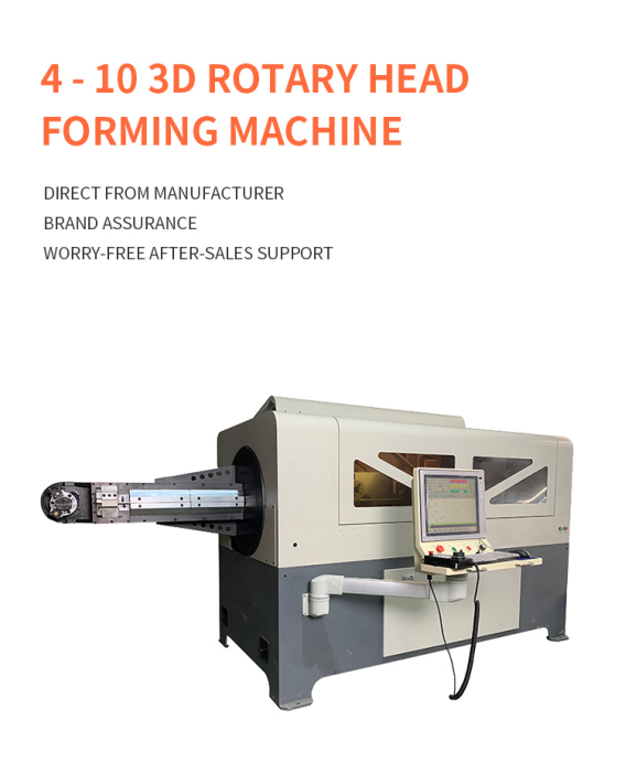
Producing a wire part that bends across several planes is very different from making a flat frame. As the geometry becomes more complex, the machine must control feeding length, bending angle, rotation and tooling position as one coordinated process. A rotary head 3D wire bending machine solves this challenge by moving the bending head around the material so the wire can remain comparatively stable during forming.
What “rotary head” means in 3D wire forming
In a rotary head configuration, the bending unit changes orientation around the wire instead of relying on the finished part to rotate through every spatial angle. The CNC program coordinates wire feed, head rotation and bending-tool movement to build the part one feature at a time.
This approach is especially useful when a component has depth, offset bends or several planes. Keeping the wire stable helps reduce uncontrolled movement as the formed section becomes longer or more asymmetrical.
The forming sequence step by step
A typical cycle begins when straightened wire is fed through the machine to the programmed length. The bending head then moves into position, completes the first bend and changes orientation for the next plane. This sequence continues until the complete geometry has been formed and the part is cut or released.
The exact motion depends on the part drawing, material, wire diameter, bend radius and selected tooling. For this reason, an accurate sample trial is more valuable than judging a machine only by its nominal wire range.
- Feed the programmed wire length.
- Position the bending tool and complete the required angle.
- Rotate or reorient the bending head for the next plane.
- Repeat the feed-and-bend sequence until the geometry is complete.
- Cut or release the part and inspect its dimensions.
Why wire stability matters
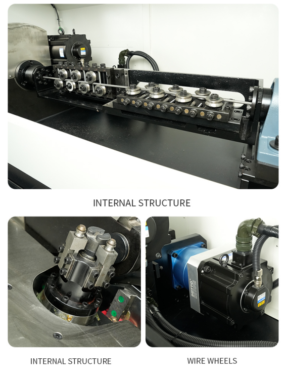
When a long or irregular workpiece is forced to rotate rapidly, its mass can create vibration and positional variation. A rotary head system is designed to reduce the need to spin that developing part through every bend. This can make the process more suitable for large frames, long parts and components whose shape becomes unbalanced during forming.
Stability does not remove the need for correct tooling, material preparation or program compensation. It gives the process a more controlled foundation, but the final result still depends on springback, wire consistency and bend-sequence planning.
Main CNC axes and what they control
A buyer does not need to select a machine simply by choosing the highest possible axis count. The important question is whether the machine has the coordinated movements required by the actual part family. A clear sample drawing allows the supplier to map each geometric feature to a machine movement.
- Wire feed controls the length between bends.
- Bending motion controls the bend angle and direction.
- Head rotation changes the forming plane.
- Tool movement or auxiliary axes may support complex radii, offsets or part release.
- Cutting separates the finished component from the incoming material.
Parts that are well suited to rotary head forming
Rotary head equipment is commonly considered for parts that cannot lie flat on a table. Typical examples include automotive seat wires, furniture frames, kitchen and bathroom hardware, supermarket display accessories, appliance supports and custom industrial wire components.
The best candidate is not defined by industry name alone. It is defined by geometry: multiple planes, meaningful depth, long formed sections or an orientation that would be difficult to produce consistently with a planar bender.
Material and tooling considerations
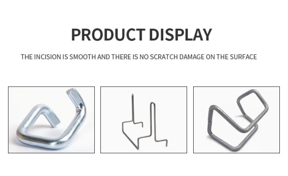
Material grade affects springback, required force, tooling wear and surface protection. Carbon steel, stainless steel and other alloys can behave differently even when their nominal diameters are identical. Round wire, shaped wire and flat profiles also need different guide and bending-tool designs.
Before ordering, provide the material specification, diameter or profile dimensions, bend radii, tolerances and surface requirements. If marks are unacceptable, this must be discussed before the tooling is designed.
For some smaller or more compact components, a 3D wire rotation bending machine may also be considered. The appropriate forming method should be selected according to part size, geometry, material behavior and the stability required during bending.
How to evaluate a sample trial
A useful sample trial should represent the difficult features of the intended production part. Measure critical distances, angles and overall geometry instead of checking only whether the machine can make a visually similar shape.
Run several consecutive pieces and compare them. Repeatability across a small batch reveals more than one carefully adjusted sample. The trial should also record cycle time, setup time, tooling changes, scrap and the operator actions required between parts.
- Confirm the approved drawing revision and measurement method.
- Check critical dimensions across multiple consecutive parts.
- Inspect bend marks, scratches, twisting and cut-end quality.
- Record real cycle time under repeatable conditions.
- Confirm how programs, tooling and setup parameters are stored.
Conclusion
A rotary head 3D wire bending machine is valuable when the product requires controlled multi-plane forming and the developing part should remain stable during the cycle. The right machine is determined by the real component, not by a keyword or axis number alone.
Send Jinchun your 3D drawing, material specification, wire diameter, tolerance and target output. A sample-based review can help determine the appropriate machine structure, tooling and forming sequence before production planning begins.