 EN
EN


Introduction
Wire thread inserts are small components, but their production requires tight coordination between wire feeding, helical forming, pitch, end geometry, and cutting. Small dimensional errors can affect installation, thread engagement, or the consistency of the finished insert. For this reason, machine selection should be based on the insert standard, drawing, material, tolerance, and installation requirement rather than on nominal size alone.
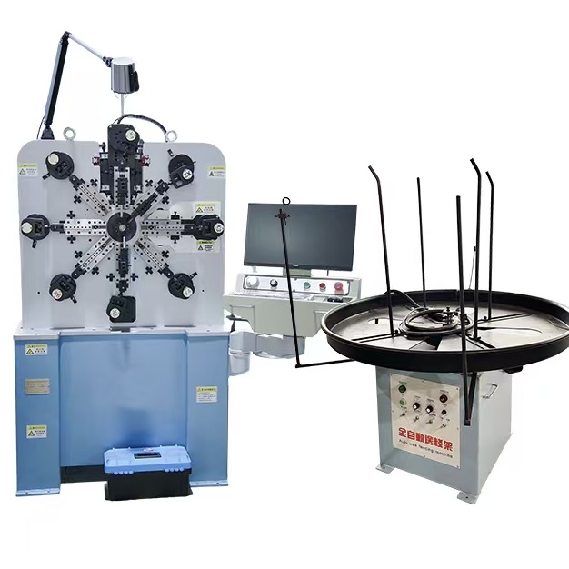
A dedicated insert-forming solution belongs to the broader family of spring making machine
technology, but the tooling and forming sequence must be configured specifically for wire thread inserts.
1. What a Tangless Wire Thread Insert Is
A tangless wire thread insert is a helically formed wire component used to reinforce or repair an internal thread. Unlike designs that rely on a conventional driving tang, a tangless insert uses an end geometry intended for its corresponding installation method. This makes end-form consistency an important manufacturing requirement.CNC wire thread insert machine
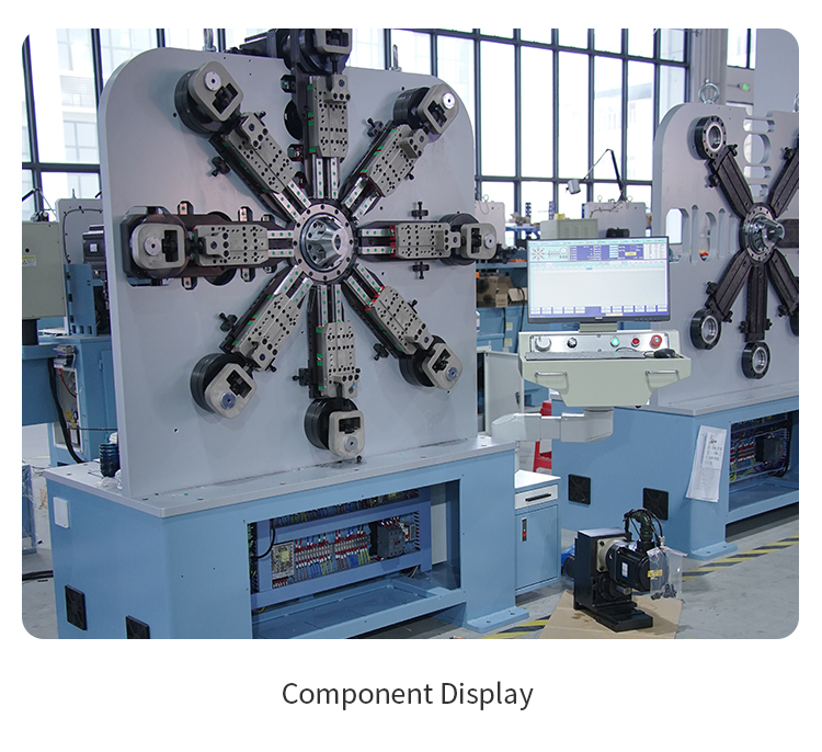
is designed as a dedicated multi-axis solution for helical wire inserts. Jinchun's published six-axis configuration is intended for M3-M14 tangless inserts, with coordinated feeding, helical forming, end processing, and cutting. The actual configuration must still be confirmed against the required insert specification.
2. Material Preparation and Wire Feeding
Stable insert production begins before the wire reaches the coiling point. Wire cross-section, material grade, tensile strength, surface condition, dimensional consistency, and spool condition all influence forming behavior. If the wire twists, feeds irregularly, or changes mechanical properties between batches, the finished insert can drift even when the CNC program remains unchanged.
The feeding system must deliver a repeatable length of wire into the forming zone. Guides should support the material without causing damaging scratches or excessive friction. For precision parts, incoming material control is part of process control.
3. CNC Coiling and Pitch Control
During coiling, the machine must coordinate feed length with the forming tool so that the helix reaches the required diameter, pitch, and number of turns. These variables are linked: changing one setting can affect overall insert length or how the insert engages with the receiving thread.
Pitch control is particularly important because a wire thread insert must function with a defined thread system. The machine setup should therefore be validated using the actual insert specification and inspection method. Programmed control improves repeatability, but it cannot replace dimensional verification.
4. Tangless End Forming
The end feature distinguishes tangless insert production from simple helical coiling. The machine and tooling must create the specified end geometry without damaging the neighboring coil or producing uncontrolled deformation. Tool access, timing, and wire springback all affect the result.
End forming should be checked for shape, orientation, burrs, and compatibility with the intended installation method. Because the part is small, magnified visual inspection or suitable gauges may be required during setup and quality control.
5. Cutting and Part Ejection
After the programmed coil and end-form sequence is complete, the insert must be separated cleanly. Cutting quality affects the final end condition and can influence installation. A poor cut may create burrs, deformation, or inconsistent overall length.
Part ejection and collection should also be considered. Small inserts can be difficult to handle manually, so the production method should prevent finished parts from becoming mixed, damaged, or lost. Collection design becomes increasingly important as output rises.
6. Critical Quality Checks
Key checks include free outside diameter, overall length, pitch, coil count where applicable, end geometry, cut condition, and visual surface quality. The inspection plan should follow the actual insert standard and customer drawing.
Dimensional inspection alone may not be sufficient. Installation testing with the specified tool and receiving thread can reveal issues that are difficult to see in a free-state part. For recurring production, retain approved samples and record the verified machine program and tooling setup.
7. Changeover Between Insert Sizes
Changing from one insert size to another may require tooling changes, guide adjustments, program selection, and renewed sample approval. The exact scope depends on the machine configuration and the relationship between the two insert specifications.
Stored CNC programs can simplify repeat orders, but operators should still verify the installed tooling, material, feed path, and first-off parts. A controlled changeover procedure reduces the risk of running the correct program with the wrong tooling or wire.
8. Information Required for Machine Selection
Provide the full insert size range, finished-part drawings, applicable standards, wire material, wire cross-section and dimensions, tolerances, end-form details, cutting requirements, and target production volume. If possible, provide physical samples and information about the intended installation method.
Also clarify whether the project is for one stable size or a family of sizes. This affects tooling planning, changeover strategy, program management, and the overall machine configuration.
Conclusion
Reliable tangless insert production requires more than forming a small helix. Wire preparation, feed accuracy, coil diameter, pitch, end forming, cutting, collection, and inspection must work as one controlled process. The machine configuration should therefore be confirmed against the actual insert standard and installation requirement.
To evaluate your insert range and required tooling, contact Jinchun
with drawings, material details, tolerances, samples if available, and target output.