 EN


Introduction
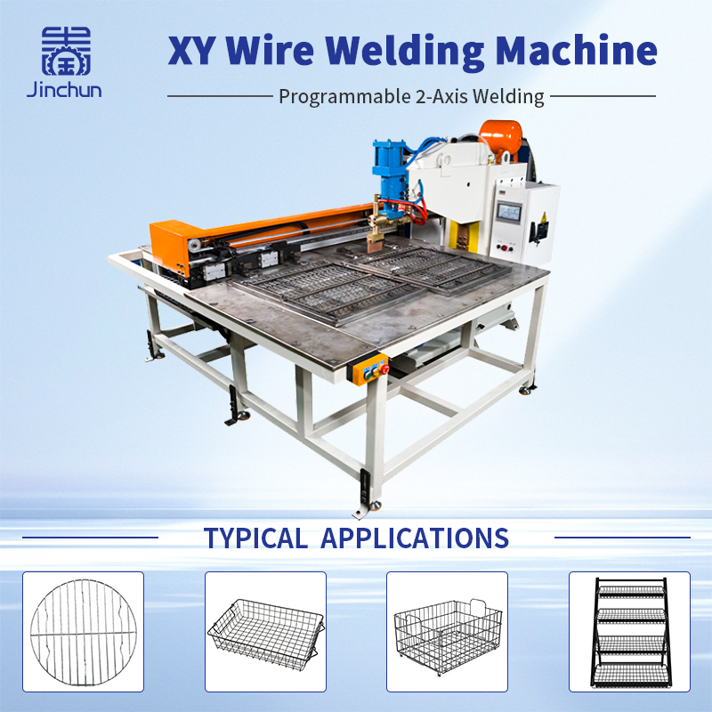
A reliable wire mesh welding fixture is essential for maintaining consistent mesh spacing and welded panel squareness during production. In XY wire mesh welding, even small positioning errors can affect the distance between wire intersections, the overall dimensions of the panel, and the quality of the finished product.
Although an XY-axis welding machine can position electrodes accurately, accurate electrode movement alone does not guarantee dimensional consistency. Wires may shift during loading, locating components may wear over time, and welding heat may cause the panel to change shape.
To achieve repeatable results, manufacturers need to coordinate fixture design, mesh spacing control, clamping, welding sequence, and dimensional inspection. The fixture should be designed around the actual panel drawing, wire specifications, weld locations, and required tolerances.
This guide explains how to design and inspect a wire mesh welding fixture to improve mesh spacing control and maintain welded panel squareness in XY wire mesh welding applications.
1. Establish Reference Points for Mesh Spacing Control
Effective mesh spacing control starts with clearly defined reference points. Before designing a wire mesh welding fixture, identify the panel's overall width and length, longitudinal wire positions, cross-wire spacing, reference edges, and diagonal dimensions.
These dimensions should follow the approved product drawing. If operators, fixture designers, and quality inspectors use different reference points, measurement results may not be consistent.
For accurate mesh spacing control, confirm whether the specified spacing refers to the center-to-center distance between wires or another measurement method. Record the permitted variation for each critical dimension and ensure that the fixture layout and inspection procedure follow the same definitions.
Clear reference points help manufacturers identify positioning errors early and reduce dimensional deviations during production.
2. Design a Wire Mesh Welding Fixture for Repeatable Positioning
A well-designed wire mesh welding fixture keeps longitudinal and cross wires in their intended positions before and during welding. Depending on the panel design, the fixture may use locating slots, pins, stops, supports, or other positioning components.
The locating features must match the actual wire layout without forcing the wires into position so aggressively that incoming-material problems are concealed.
Wire diameter, straightness, and cut length should be checked before production because variations in these characteristics can affect how the wires sit in the fixture. Worn locating pins, loose stops, or debris inside locating slots can also cause inconsistent mesh spacing.
For manufacturers producing multiple panel designs, replaceable locating components can simplify changeovers. However, each fixture configuration should have a clear identifier and an approved layout. After installing or replacing locating parts, verify their positions before starting production.
3. Coordinate XY Wire Mesh Welding with Fixture Design
In XY wire mesh welding, the fixture and the machine must work together to maintain accurate wire positioning while allowing the electrodes to reach each welding intersection.
The fixture should provide sufficient support to prevent unwanted wire movement without obstructing the electrode's approach path. Clamps, stops, and locating components must also avoid interference with the machine's programmed movements.
Clamping force is another important consideration. Insufficient clamping may allow wires to move during electrode contact or welding. Excessive force, on the other hand, may bend, mark, or distort the wire.
The position and sequence of the clamps should therefore be evaluated under actual operating conditions. Check whether wires remain stable when the fixture closes, the electrodes contact the joints, and the machine moves between weld points.
A suitable fixture layout improves positioning repeatability and supports consistent results in XY wire mesh welding.
4. Control the Welding Sequence to Maintain Welded Panel Squareness
Welded panel squareness depends on more than the accuracy of the initial wire arrangement. The welding sequence and heat distribution can also influence the final panel geometry.
If welding is concentrated in one area, localized heating may cause uneven dimensional changes. Depending on the material, wire diameter, joint arrangement, and welding parameters, the panel may bow or develop differences between its diagonals.
To improve welded panel squareness, test the welding sequence using representative samples. Observe whether the wires shift during welding and whether the panel's width, length, grid spacing, or diagonal measurements change as the process progresses.
Record the sequence and welding conditions used for accepted samples. If dimensional deviations occur, evaluate fixture positioning, clamping, and welding sequence separately. This approach helps identify the actual cause rather than adjusting the fixture to compensate for an unrelated process problem.
5. Inspect Mesh Spacing and Welded Panel Squareness Before and After Welding
Dimensional inspection is necessary to verify whether a wire mesh welding fixture is performing as intended.
Before welding, inspect the wire arrangement in the loaded fixture. After welding, measure the same critical dimensions and compare the results. This comparison helps distinguish incoming-material variation and loading errors from dimensional changes introduced during welding.
For mesh spacing control, measure selected intervals between adjacent wires and check the consistency of the grid pattern. For welded panel squareness, measure the overall width and length and compare both diagonals when the panel design requires a square or rectangular shape.
Use the same measurement points and methods throughout the inspection process. Record actual measurements rather than simply marking a panel as accepted or rejected.
If deviations occur repeatedly at similar locations, investigate the relevant fixture datums, locating components, clamping conditions, and welding parameters. Measurement records can help reveal patterns that are difficult to identify through visual inspection alone.
6. Standardize Wire Mesh Welding Fixture Changeovers
When one XY-axis welding machine produces several mesh panel designs, fixture changeovers must be controlled to maintain repeatable positioning.
Each wire mesh welding fixture should have a unique identifier linked to the corresponding product drawing and revision. Locating pins, stops, and clamps should be installed in their approved positions and secured before production begins.
Keep obsolete fixture layouts separate from current configurations to reduce the risk of using an incorrect setup. A changeover checklist should confirm the fixture version, component positions, fastening condition, and relevant machine settings.
After each changeover, produce a trial panel and verify mesh spacing, overall dimensions, and welded panel squareness against the approved acceptance criteria.
Quick-change fixtures can reduce setup time, but repeatability remains the priority. A fast changeover is only effective when the new configuration consistently produces panels that meet dimensional requirements.
7. Verify Repeatability with Consecutive Welded Panels
A single acceptable panel does not establish that mesh spacing control and welded panel squareness will remain consistent throughout production.
During machine commissioning or a fixture change, inspect a planned series of consecutive panels. Record mesh spacing, overall dimensions, diagonal measurements, and any observed wire movement or panel distortion.
Compare the results with the agreed drawing tolerances. If the measurements vary significantly between panels, review the wire material, fixture condition, clamping method, welding sequence, and inspection procedure.
Define when another dimensional check is required, such as after a wire batch change, fixture repair, electrode maintenance, or welding program revision.
Keeping an approved sample and its inspection records provides a practical reference for repeat orders and helps maintain consistent quality in XY wire mesh welding.
Conclusion
A properly designed wire mesh welding fixture helps manufacturers achieve reliable mesh spacing control and consistent welded panel squareness. For XY wire mesh welding applications, fixture positioning, wire condition, clamping force, welding sequence, and dimensional inspection must work together.
Before routine production, validate the fixture and welding process using actual wire materials and representative panels. Confirm that mesh spacing and diagonal dimensions remain within the required tolerances across consecutive samples.
Looking for a suitable solution for your wire mesh welding application? Contact Jinchun and share your panel drawing, wire material, wire diameter, mesh spacing, and production requirements. Our team can help evaluate your application and recommend a suitable welding solution.
Table of Contents
- Introduction
- 1. Establish Reference Points for Mesh Spacing Control
- 2. Design a Wire Mesh Welding Fixture for Repeatable Positioning
- 3. Coordinate XY Wire Mesh Welding with Fixture Design
- 4. Control the Welding Sequence to Maintain Welded Panel Squareness
- 5. Inspect Mesh Spacing and Welded Panel Squareness Before and After Welding
- 6. Standardize Wire Mesh Welding Fixture Changeovers
- 7. Verify Repeatability with Consecutive Welded Panels
- Conclusion