 EN
EN


Introduction
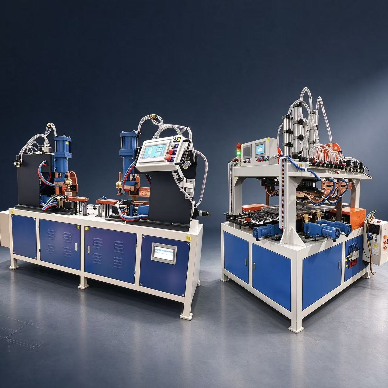
A wire shelf production line should be planned from the finished product backward. A shelf may look simple, but it can contain an outer frame, cross rods, bottom mesh, reinforcing members and connection features, each with a different forming or welding requirement. Choosing machines one by one without mapping the complete process can create an unbalanced line. The better approach is to break down the shelf, define the quality standard for each component, and then match bending, welding, handling and inspection equipment.
1. Break the Shelf into Components
Start by identifying every component and how it is joined. Separate the outer frame, support rods, bottom mesh, reinforcing bars and connectors. Record material, wire diameter or section, dimensions and the number of each component per finished shelf. This component map determines which parts need straightening, which need bending, which can be welded as subassemblies and where dedicated fixtures are required.
2. Straightening and Material Preparation
The line may start from coil wire or pre-cut straight bars. Coil-fed production normally needs controlled pay-off, straightening and cutting before some welding or secondary operations. Straightness and cut-length consistency matter because errors at this stage can accumulate during bending and fixture loading. Material surface condition should also be protected if the final shelf is plated, coated or polished after fabrication.
3. Frame Bending
Outer frames and other two-dimensional components can often be produced with a CNC 2D wire bending machine when the geometry, material and diameter fit the machine’s working range. Dedicated forming equipment may be better for very simple high-volume parts or special sections. When selecting the bending process, consider bend radius, number of bends, dimensional tolerance, changeover between SKUs and whether the part must remain flat before welding.
4. T-Joint Welding for Supports
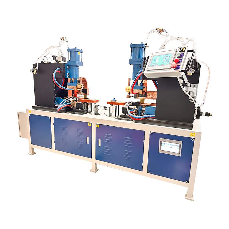
Cross rods and reinforcing members often create repeated T-joints on the frame. A double-head T-welding machine for shelf can reduce repeated positioning when two weld points have a stable relationship. Fixture design should control rod spacing, frame position and flatness while allowing fast loading. For more detail on the welding logic, see our guide to double-head T-welding for shelf frames.
5. Bottom Mesh Welding
The bottom mesh can be produced with different welding approaches depending on mesh size, weld pattern, wire diameter, panel dimensions and required output. Automatic wire welding machines include row welding, XY-axis systems, gantry welders and dedicated shelf bottom-net equipment. A regular mesh with repeated weld positions may justify a dedicated high-output arrangement, while flexible product mixes may benefit from programmable XY welding. The correct choice comes from the actual weld map and takt-time target.
6. Handling Between Stations
Material handling is part of line design. Small or medium production may use operators and dedicated carts between bending and welding stations. Higher output may justify transfer tables, conveyors or automatic loading. The key is to protect part geometry and maintain orientation. A fast machine can still sit idle if operators cannot load it consistently or if semi-finished frames arrive tangled, mixed or deformed.
7. Quality Control Across the Line
Define inspection points before commissioning. After bending, check frame dimensions, bend angles and flatness. After T-joint welding, check weld location, deformation and joint strength. After bottom-mesh welding, verify mesh spacing, panel dimensions and missing or weak welds. Before final assembly, confirm that the frame and mesh fit together without forcing. A line should control variation at each stage instead of relying on final inspection to catch every problem.
8. How to Calculate the Required Output
Required capacity should be calculated from the finished shelf target and the bottleneck process. Convert the daily or hourly target into the number of frames, mesh panels and support components needed. Then include loading time, welding or bending cycle, changeover, inspection and realistic utilization. If one station produces much faster than the next, buffers or multiple machines may be required. The goal is balanced output, not the highest standalone speed on one specification sheet.
9. Project Information Checklist
For a line proposal, send finished-product drawings or samples, all SKUs, material and wire sizes, component quantities per shelf, weld-point layout, dimensional tolerances, required output, available factory space, labor plan and preferred automation level. Photos or videos of the current production method can reveal handling and quality problems that drawings alone do not show. Also state whether packaging, coating or assembly is inside or outside the requested scope.
Conclusion
A shelf production line is not simply a group of machines placed together. Bending, T-joint welding, bottom-mesh welding, handling and inspection must be balanced around the same product and takt time. Jinchun’s production line solutions can be reviewed from the finished shelf backward so that each station matches the component, quality requirement and target capacity. Send your shelf drawing and production target to discuss a suitable line configuration.
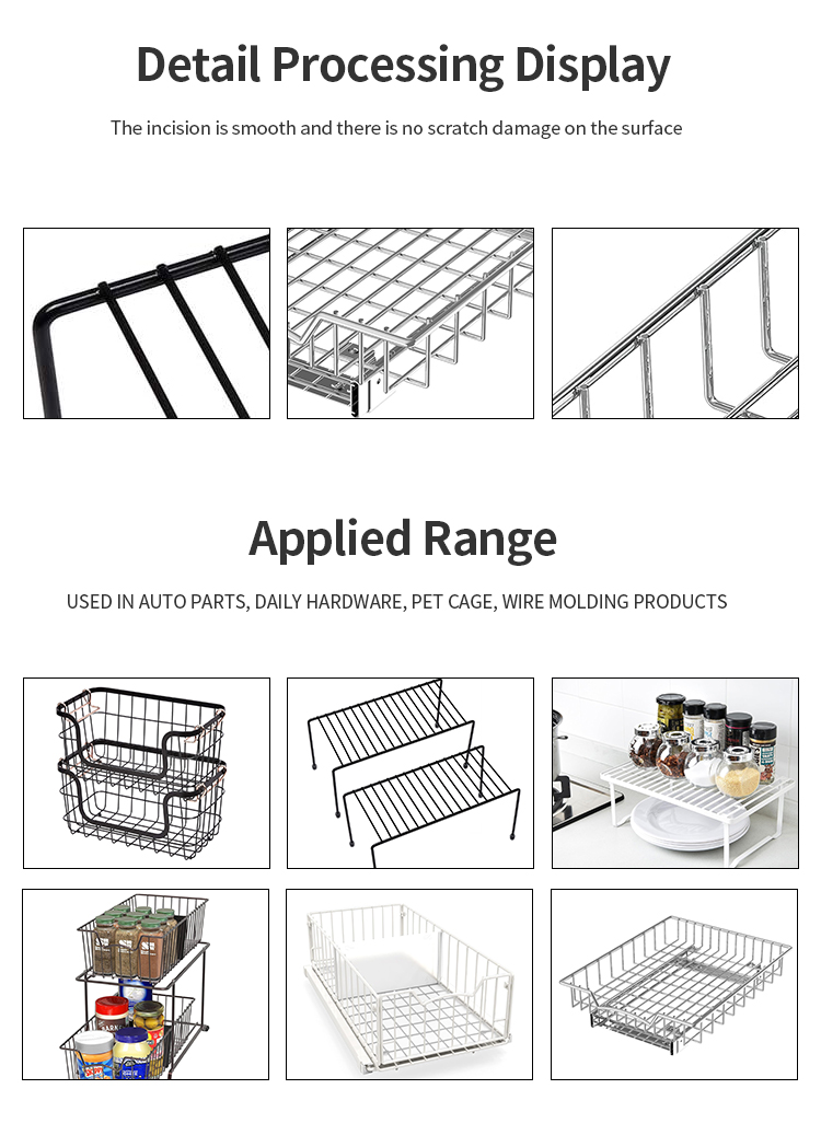
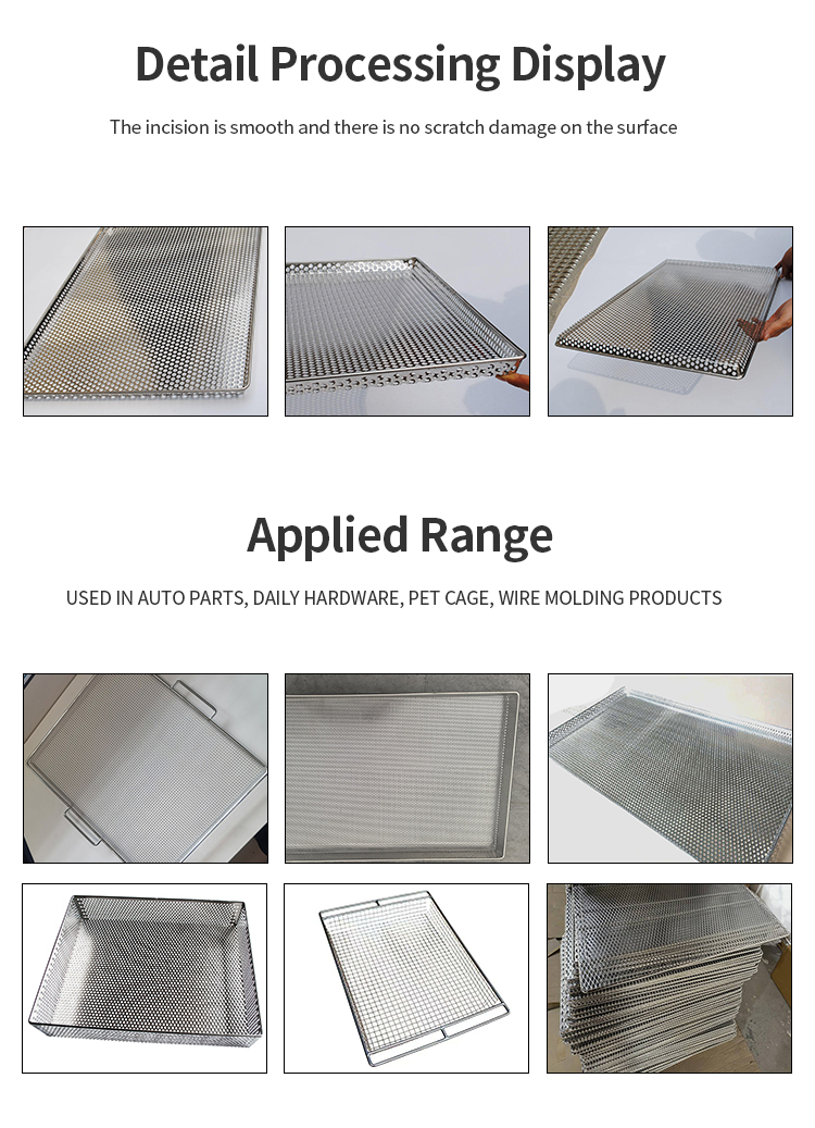
Table of Contents
- Introduction
- 1. Break the Shelf into Components
- 2. Straightening and Material Preparation
- 3. Frame Bending
- 4. T-Joint Welding for Supports
- 5. Bottom Mesh Welding
- 6. Handling Between Stations
- 7. Quality Control Across the Line
- 8. How to Calculate the Required Output
- 9. Project Information Checklist
- Conclusion