101, Building 9, Jicheng Science And Technology Innovation Park, No. 25, Sanle East Road, Shunjiang Community, Beijiao Town, Foshan, Guangdong, China +86-18038626853 [email protected]
101, Building 9, Jicheng Science And Technology Innovation Park, No. 25, Sanle East Road, Shunjiang Community, Beijiao Town, Foshan, Guangdong, China +86-18038626853 [email protected]

Springback is one of the most common challenges in CNC wire bending.
A wire may be bent to the programmed angle, but after the forming force is released, it can partially return toward its original shape. The result may be an incorrect angle, dimensional deviation, or inconsistent parts during continuous production.
For manufacturers producing wire frames, brackets, hooks, automotive wire components, furniture parts and other precision wire products, controlling springback is essential for stable production.
The good news is that springback is not simply a machine problem. It can be evaluated and controlled through material data, tooling, bend sequence, forming parameters and compensation.
When a wire is bent, the material is subjected to both plastic and elastic deformation.
The plastic deformation creates the permanent bend, while the elastic deformation tends to recover after the forming force is released. This recovery is what we call springback.
The amount of springback can vary depending on several factors:
This is why two wires with the same nominal diameter may not produce exactly the same result if their material properties are different.
As Jinchun's recent guide on CNC wire bending machine selection explains, wire diameter alone is not enough to determine forming requirements. Material grade, strength, geometry and tolerances should also be considered when evaluating a machine configuration.
Before adjusting the CNC program, first understand the wire being formed.
At minimum, the machine supplier should know:
Different materials can respond differently to the same bending operation.
For example, higher-strength wire may require greater forming force and may show different springback behavior from softer wire. A change in material condition between production batches can also affect previously established compensation settings.
For this reason, avoid selecting a machine based only on the maximum wire diameter listed in a specification sheet.
The actual product drawing and wire specification should be evaluated together.
Tooling has a direct influence on the final shape of a bent wire.
The bending die, forming roller, support position and contact area all affect how the wire behaves during forming.
If the wire is not properly supported, it may move or deform in an uncontrolled way during bending. This can make it difficult to maintain consistent angles and dimensions.
For precision wire forming, the tooling should therefore be selected according to:
A suitable tooling setup provides a more stable forming process and gives the CNC system a better foundation for compensation.
For a simple 2D wire part, the bending sequence may appear straightforward.
However, as the number of bends increases, the sequence can have a significant influence on the final dimensions.
One bend can change the position and orientation of the wire before the next bend takes place. For complex parts, an unsuitable sequence may also create interference between the wire, tooling and previously formed sections.
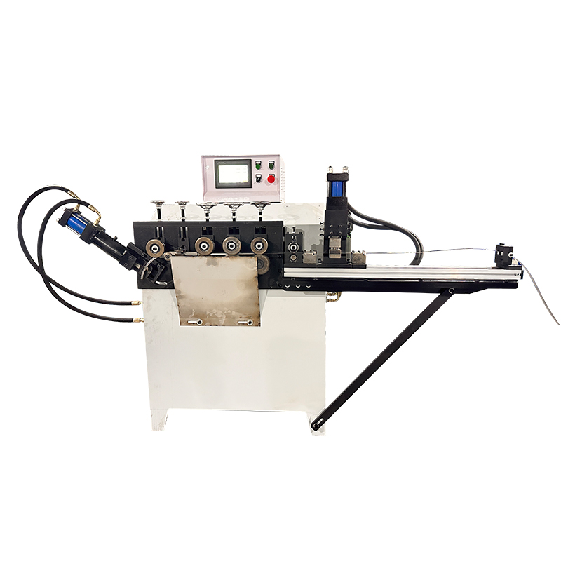
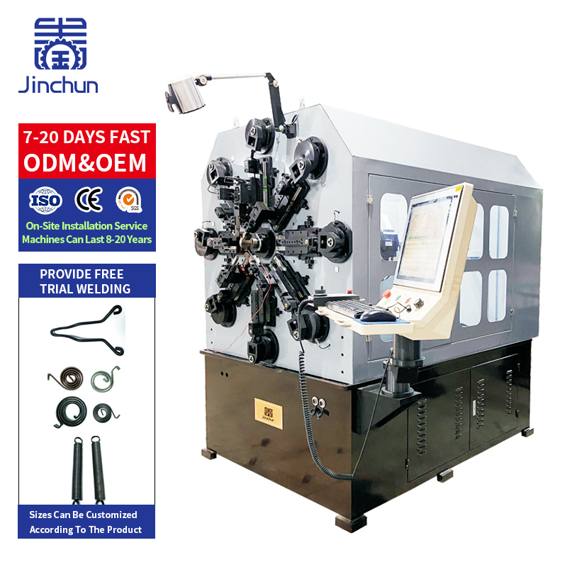
A CNC 2D wire bending machine is designed for programmable forming of planar wire shapes and frames. The actual machine configuration should be selected according to the product geometry, wire material, diameter, dimensions and production requirements.
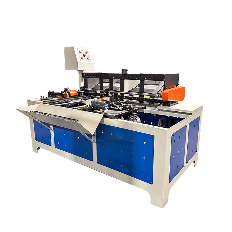
For parts with multiple planes or complex spatial geometry, a CNC 3D rotary head bending machine can coordinate wire feeding, bending and head rotation to build the required shape.
Therefore, the bend sequence should be considered together with the machine configuration rather than adjusted as an isolated parameter.
Once the initial sample is produced, measure the actual result against the target drawing.
For example:
Target angle → Actual angle → Difference → Compensation → New sample
If the programmed angle is 90° but the finished part opens slightly after forming, the CNC program may require an appropriate compensation adjustment.
The important point is that compensation should be based on actual test results, not on a universal correction value.
A practical compensation process may look like this:
Run the initial CNC program using the selected tooling and material.
Check critical angles, lengths, radii and other important dimensions against the drawing.
Determine where the actual part differs from the target dimension.
Modify the relevant bending or compensation parameters according to the measured result.
Run another part and compare the result with the previous sample.
Do not stop after achieving one acceptable sample. Produce multiple consecutive pieces to confirm that the result is repeatable.
This is particularly important before moving from prototype production to mass production.
A single accurate sample does not necessarily mean the process is stable.
For production, manufacturers should check whether several consecutive parts maintain the required dimensions.
A useful sample trial should therefore record:
| Item | What to Check |
|---|---|
| Wire material | Grade and condition |
| Wire diameter | Actual diameter |
| Bend angle | Target vs. measured angle |
| Bend radius | Required vs. actual radius |
| Dimensions | Critical dimensions |
| Compensation | Program adjustment |
| Repeatability | Results across multiple samples |
| Cycle time | Production efficiency |
| Tooling | Wear and stability |
The purpose of a sample trial is not simply to prove that the machine can bend one piece. It is to determine whether the complete process can consistently produce the required part.
Jinchun's recent sample-trial guidance similarly focuses on accuracy, repeatability, cycle time, tooling and changeover when evaluating a CNC wire bending machine before purchase.
The right machine depends on the geometry of your product.
For relatively flat products, a CNC 2D wire bending machine can be considered for programmable forming of planar wire shapes and frames.
For products involving multiple planes, offsets or more complex spatial geometry, a CNC 3D rotary head bending machine may be more appropriate. Its rotary head coordinates the forming direction with wire feeding and bending movements.
The machine should therefore be selected according to the actual product rather than simply choosing the machine with the largest advertised capacity.
A practical selection formula is:
Product geometry + material + wire diameter + tolerance + production volume = machine configuration
Springback cannot always be predicted accurately from a material name or wire diameter alone.
For a new product, sample testing allows the manufacturer and machine supplier to evaluate the actual interaction between:
Material + Tooling + Machine + Program + Bend Sequence
This is especially important when:
A real sample or drawing gives the machine supplier much more useful information than a product name alone.
Springback is a normal consideration in CNC wire bending, but it should not be treated as an unavoidable production defect.
Stable forming depends on understanding the material, selecting suitable tooling, planning the bending sequence, applying compensation based on measured samples and verifying repeatability before mass production.
The most reliable approach is to evaluate the complete forming process, rather than looking only at machine capacity or wire diameter.
If you are developing a new wire product, send us your drawing, material grade, wire diameter, tensile strength, bend radius and required tolerance.
Jinchun can evaluate the springback risk and recommend a suitable CNC wire bending machine, tooling and compensation method for your application.
 Hot News
2026-09-19
2026-09-18
2026-09-17
2026-09-16
2026-09-15
2026-09-14
 EN
EN