 EN


Introduction
A wire bending machine must be checked against the full forming sequence, not only the final part dimensions.
A three-dimensional wire component may look correct in a drawing, yet be difficult to produce if a previously formed arm blocks the bending tool, the workpiece collides with the machine, or the finished part cannot be unloaded. These risks are especially important for parts with bends on several planes, long extensions, tight offsets or partially closed shapes.
Sequence planning connects product geometry with the actual movements of the wire, bending tools and machine head. It should begin before production programming and be verified with the intended material and tooling. The goal is not simply to make every bend, but to make them in an order that is repeatable, accessible and practical for production.
1. Map the Finished Part Geometry
Start with the latest approved drawing or a clearly dimensioned sample. Mark every bend, straight length, plane change, offset and end feature. Identify which dimensions control assembly or function and which are less critical. A 3D part should be reviewed from multiple views because a bend that appears clear in a front view may overlap another arm when viewed from above or from the side.
Pay special attention to long arms, hooks, loops and regions that become partially closed during forming. These features can restrict access to later bends. If the drawing does not show the bend radii, wire centerline or critical tolerances clearly, clarify them before programming rather than relying on visual estimates. A dimensioned model or drawing makes sequence discussions with the machine supplier more efficient.
2. Define the Starting End
The first bend affects how the remaining wire can be supported and accessed. Compare possible starting ends and ask what the early bends will do to the free length available for later operations. Beginning at one end may keep the wire easy to feed, while starting at the other may reduce the chance that a long formed arm obstructs the tool.
Do not select the starting end only because it seems natural from the drawing. Review the complete order, including the final bend and cut-off. Consider whether the wire can still be advanced reliably after the first features are formed, and whether the partially completed component can pass through each later movement without being forced or twisted.
3. Review Tool Access and Clearance
Each bend needs enough space for the forming tool to approach, engage the wire and withdraw. Check the clearance between the tool, previously formed sections, adjacent bends and the machine structure. Small gaps in the finished product may be difficult to produce if the tooling cannot enter or retreat along a workable path.
Include the tool body and its movement, not only the point where the wire is bent. A sequence may be geometrically possible but mechanically impractical if the tool must pass through a narrow opening. For complex parts, review tool access at each intermediate stage and identify where a different bend order, tooling shape or customized setup may be required.
4. Plan Rotation Between Bends
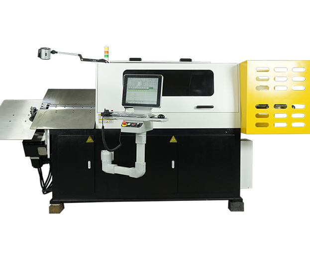
A 3D rotary head bending machine should be evaluated for tool access and clearance throughout the selected bending sequence.
Three-dimensional forming requires coordinated changes in feed position, bending direction and orientation. The planned rotation must be assessed throughout the sequence, because the workpiece's swept space can be much larger than its final outline. Long arms and already formed loops may swing into tools, guards or the machine frame during a rotation.
Compare how the chosen configuration creates each plane change and confirm which component moves during the operation. Do not assume that a part will clear the machine simply because the final shape fits within the nominal working area; verify the full movement envelope with the actual drawing and tooling.
5. Account for Part Support and Unloading
Long or unbalanced workpieces may sag, vibrate or shift if they are not supported appropriately. Consider the wire's length, stiffness and the position of its center of mass as the part develops. Any support must help control the workpiece without blocking tool access or interfering with programmed movement.
Unloading is part of the forming plan, not an afterthought. A completed part may be trapped by a closed shape, a long arm or the orientation in which the final bend is made. Decide how the operator or automatic handling arrangement will remove the part safely and consistently. If manual removal is required, leave sufficient hand access and avoid a sequence that makes the operator twist or force the finished component.
6. Verify the Sequence in a Trial
Use a sample trial to confirm the proposed process with the specified wire grade, diameter and tooling. Follow the manufacturer's commissioning and safety procedures. Observe each movement at a controlled pace before assessing the complete cycle. Look for contact marks, tool obstruction, wire slippage, unexpected springback and difficulty removing the part.
Record the result of each change rather than adjusting several steps at once. If interference occurs, note the exact bend or rotation where it begins, then review the order, tool access and support arrangement. Dimensional inspection should include the critical lengths, angles, offsets and final assembly interfaces. A successful first sample is a starting point; repeated samples help establish whether the sequence is stable.
7. Record the Approved Setup
Once the sequence is confirmed, preserve the program version, drawing revision, material specification, tooling list and inspection results together. Record any operator notes about loading, support and unloading. This prevents a later run from using a program that belongs to an earlier drawing or a different tool arrangement.
Where several products share similar geometries, do not assume their sequences are interchangeable. Small differences in arm length or bend position can change the clearance envelope. Keep change history and identify who approved the final sample. These records help maintenance and production teams restore the correct setup after a changeover or repeat order.
Conclusion
Please contact Jinchun with your drawing, material specification and production requirements.
The most reliable 3D wire bending sequence is the one that respects the finished geometry and remains executable at every intermediate stage. Review bend order, tool access, rotation clearance, support and unloading together, then validate the process with actual material and tooling.